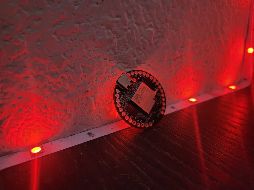
What You Need
Hardware
- A IndusBoard coin
- USB C cable
- Computer running Windows, Linux, or macOS.
Software
To start using the Indus Board install Arduino IDE on your computer. To install the Arduino IDE kindly click here.
Install the board
Kindly follow the steps below to install IndusBoard coin on Arduino IDE:
- Open Arduino IDE 2.0
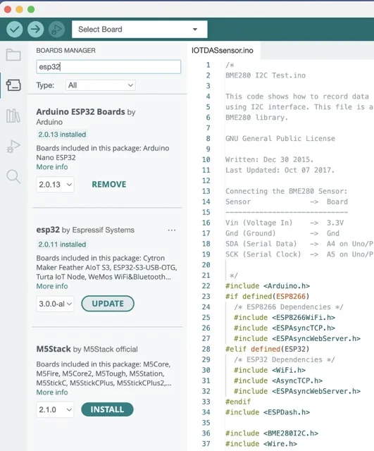
- Go to Board manager from the left panel
- Search for ESP32 in the search box
- Click on ESP32 by Expressif Systems and select the latest version from the dropdown
- Click on the install button
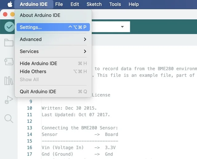
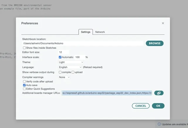
It might take a few seconds to install fully. If you have already installed the ESP32 board on Arduino IDE kindly check the version and update to the latest version.
Still confused? Click here for more details.
Plugin the board for the first time
To get started with the board for the first time kindly follow the steps below.
- Plug your board to the computer or your laptop via USB type C cable.
- You will notice a white LED glowing on the board indicating that the board is connected to your system successfully.
- To check the com port to which the board is connected open the device manager from the search menu of your system.
- Scroll down and click on ports.
- You will see a USB serial device with the com port in the bracket.
- Open Arduino IDE 2.0
- From the dropdown at the top click on select other board and port. Refer to Figure below
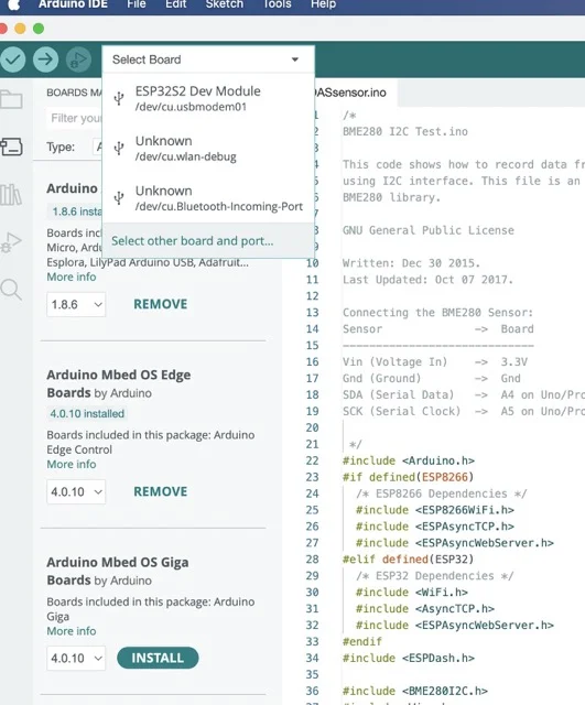
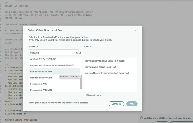
- A window will open with boards and ports.
- Search for ESP32S2 in the search box for boards.
- Scroll down and select ESP32S2 dev module.
- From the port column select the same port you saw with the board in device manager.
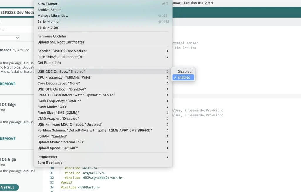
Your board is installed and selected on Arduino IDE now. Before getting started, enable USB CDC (Communications Device Class) on Arduino IDE that allows you to communicate to the board like in a serial interface. To do so follow simple steps given below.
- Open Arduino IDE 2.0
- Click on tools at the op panel.
- Go to USB CDC on boot.
- Click on enabled to enable serial communication.
Congratulations! You have completed all the steps successfully and you can begin with your first code on the IndusBoard coin.
Sleep Modes
Light-sleep mode: In Light-sleep mode, digital peripherals remain operational, allowing access to GPIOs for tasks like LED blinking, while preserving their internal states. This mode enables the system to resume operation quickly and efficiently.
Deep-sleep mode: In Deep-sleep mode, the CPUs, most of the RAM, and all digital peripherals clocked are powered off. The only active components are the RTC controller, ULP coprocessor, and the RTC’s FAST and SLOW memory.
The internal sensors, including the magnetometer, accelerometer, and current sensors, consume minimal power in deep sleep mode. They operate at 3 microamps in sleep mode and only 0.83 milliamps during active use, making them highly energy-efficient.
For more information, click here
Migrating The Arduino and ESP Project To Indusbaord
The Indusbaord is compatible with Arduino IDE and most of the Sensor and other libraries that work with Arduino and ESP 32 will also Work with INDUSBOARD. You can migrate and use most of the Arduino and ESP projects and Codes directly to INDUSBAORD. Here Is How you do it.
Project Without Pheperials
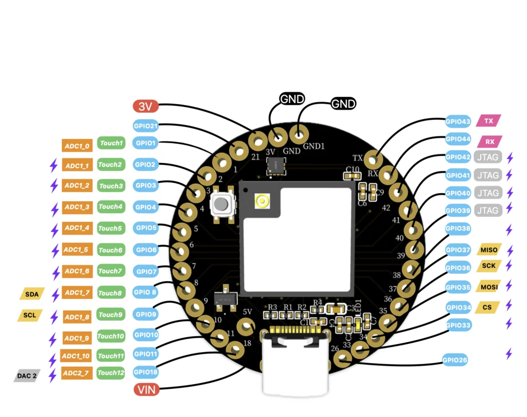
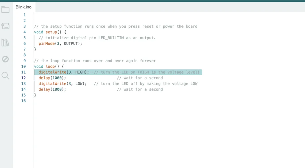
There are Projects that have simple I/O input-out output and have the Anaoug and digital output sensors or PWM signal-based controller all those projects and codes can directly run and work with Indusbaord. To migrate those projects all you need to to change the Baord name to ESP32S2 and then Select the COM Port then you can compile and upload the code the connection like you do in Arduino will be the same as you do in Arduino IndusBaord have 1 to 13 I/O pins that work similar and more advance like Arduino. In Arduino UNO digitals are only used as digitals or PWM but here they can be used as digitals, analoug also as touch sensors. If the code has the analoug read functions then you can change the I/O name with any ADC pins of INDUSBAORD almost all I/O pins on Indusbaord Coin have both analoug and digital and PWM as well. You can check the pinouts of the board here:-https://indus.electronicsforu.com/pinouts/
Project With Pheperials
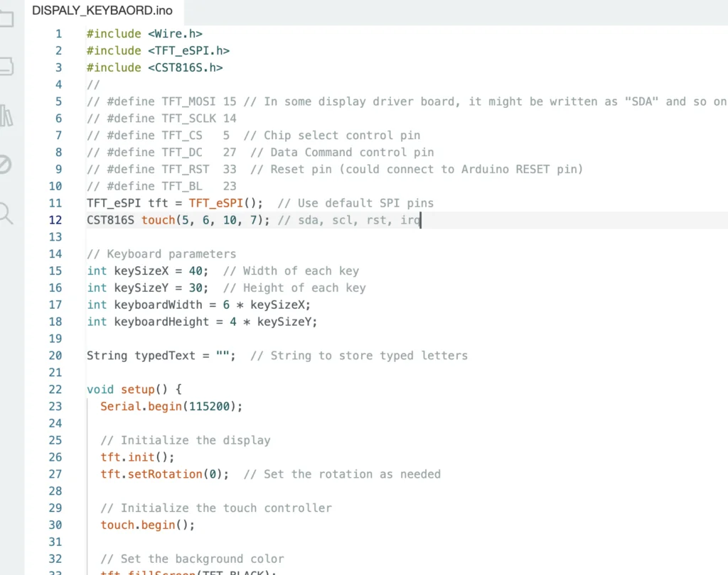
If your project includes peripherals suppose you are using the I2C-based OLED, Sensor or SPI-based TFT display or Sensor the same code goes with Indusbaord in most cases and works well with Indusbaord you only need to select the board as ESP32S2 as board and then need to compile. The pin connection becomes different. If the PIn connection is not defined in the code then it takes as default I2C and spi pins on the board i.e
For I2C default pin is 8 SDA 9 SCL and for SPI it uses 34 to 37 as you can see in the board pinouts below https://indus.electronicsforu.com/pinouts/
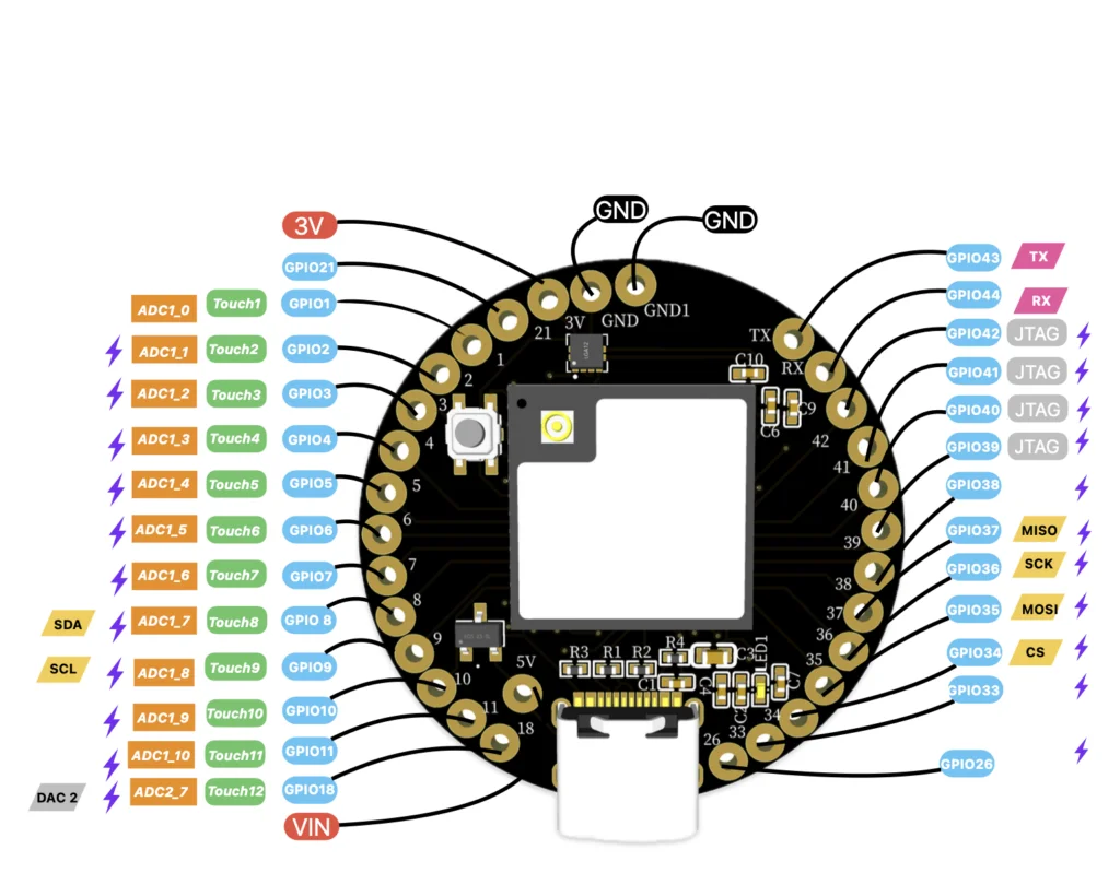
But if the pin is defined in code then you can use any of the GPIO on board as SPI and i2C by defining that pin in code and using that pin as the pheperials like in the following code snippet.
Migrating ESP32 Project to Indusbaord
The Indusbaord have an ESP32S2 Processor that has 2 more co-processors ie ULP RISC-V processor all the functions and code that you run on NODE MCU and Node32S and other ESP32-based board codes most of them will also work with the INDUSBAORD Indusbaord Code which has the function of using CO- Processor for ultra-low Power project code will not run on other boards it only run on IndusBoard.
NUTSELL:- Most of the WIFI And Other ESP 32 and ESP8266 projects will work with IndusBoardbut INDUSBAORD extra function based will not run on another board it only works with IndusBoard.
As earlier described for migrating the project you only need to select the board as ESP32S2 and upload the code. If it has a defined pin for peripherals then you can use any pin of INDUSbaord for that peripherals otherwise you can default peripherals pins of Indusbaord according to the pinouts diagram.
How to use sleep modes in Arduino IDE
To upload code while the main processor is in deep sleep mode, unplug the device and simultaneously press the reset button on the board. While holding the reset button, plug the device back in. This action puts the board into download mode, allowing for code uploading.
RTC based sleep:
esp_sleep_enable_timer_wakeup(10 * 1000000); // 10 seconds
esp_deep_sleep_start();
GPIO touch based sleep and wakeup:
The RTC IO module is designed to trigger a wakeup in response to a touch sensor interrupt. To enable wakeup from a touch sensor interrupt, users must configure the touchpad interrupt before the chip enters Deep-sleep or Light-sleep modes.
#include <esp_sleep.h>
#include <Arduino.h>
#define TOUCH_PIN 2 // Replace T0 with the specific touchpad pin you want to use
void setup() {
Serial.begin(115200);
// Configure touchpad wakeup
esp_sleep_enable_touchpad_wakeup();
touchAttachInterrupt(TOUCH_PIN, touchInterrupt, 50); // Attach touch interrupt to the specified pin
}
void loop() {
// Your main code here
// Enter deep sleep
Serial.println(“Entering deep sleep…”);
esp_deep_sleep_start();
}
void touchInterrupt() {
// Callback function for touchpad interrupt
// This will be called when touch is detected on the specified pin
}
External wakeups:
The RTC IO module has the capability to initiate a wakeup when one of the RTC GPIOs reaches a specific logic level. As part of the RTC peripherals power domain, RTC peripherals remain powered on during Deep-sleep if this wakeup source is activated.
esp_sleep_enable_ext0_wakeup(GPIO_NUM_27, LOW); // Replace GPIO_NUM_27 with the GPIO pin number
esp_deep_sleep_start();
Light sleep:
esp_sleep_enable_timer_wakeup(10 * 1000000); // 10 seconds
esp_light_sleep_start();
Deep sleep:
esp_sleep_enable_timer_wakeup(10 * 1000000); // 10 seconds
esp_deep_sleep_start();
ULP Coprocessor Programming
To use the ULP (Ultra Low Power) coprocessor on ESP32-S2 for tasks like blinking an LED, we must write a program in ULP assembly language and then load and run it from the main application. Here’s an example of how to do this with the ESP-IDF framework:
#include <Arduino.h>
#include “ulp_main.h” // Header file generated by ESP-IDF build system
RTC_DATA_ATTR int bootCount = 0;
void setup() {
Serial.begin(115200);
delay(1000);
bootCount++
Serial.printf(“Boot count: %d\n”, bootCount);
// Initialize LED pin
pinMode(LED_BUILTIN, OUTPUT);
// Load and run the ULP program
if (bootCount == 1) {
Serial.println(“Starting ULP program”);
ulpLoadBinary();
ulpRun();
}}
void loop() {
// Enter deep sleep
Serial.println(“Entering deep sleep…”);
esp_deep_sleep_start();
}
In this example, we include the ulp_main.h header file, which is generated by the ESP-IDF build system and contains function prototypes for loading and running the ULP program. We use a bootCount variable stored in RTC memory to ensure that the ULP program is loaded and run only on the first boot by keeping track of the number of boots.
Now, let’s create the ULP assembly program ulp_main.S:
#include “ulp_macros.h”
.section .ulp.text,”ax”,%progbits
.global entry
entry:
move r3, 1 // Set GPIO to output
wr_reg rtc_gpio_out, r3
loop:
set r3, 1 // Toggle GPIO
xor r3, r3, r3 // Delay
set r3, 1 // Delay
nop
set r3, 1 // Delay
nop
set r3, 1 // Delay
nop
set r3, 1 // Delay
nop
set r3, 1 // Delay
nop
set r3, 1 // Delay
nop
wr_reg rtc_gpio_out, r3
set r3, 1 // Delay
nop
set r3, 1 // Delay
nop
set r3, 1 // Delay
nop
set r3, 1 // Delay
nop
set r3, 1 // Delay
nop
set r3, 1 // Delay
nop
nop
nop
nop
nop
nop
nop
j loop // Loop indefinitely
How to power IndusBoard Coin with battery
When using the WiFi feature, it’s important to note that the USB connection may not provide sufficient power for extended periods due to the higher power consumption of WiFi. In such cases, it is advisable to switch to a battery for prolonged WiFi usage.
The board can be powered using a 3V, 3.3V, or 3.6V battery by connecting it to the 3V and GND pins on the board. For safety, ensure that you use either the USB or the battery for power, but not both simultaneously. If you need to update the code, disconnect the battery, upload the code, and then reconnect the battery.
Additionally, you can incorporate a battery charging circuit by utilizing the 5V and GND pins on the board.

